Worked Example - Setting up a simple Force Field Analysis for H2O
There are various ways a force field calculation can be set up;
the calculation worked through here is a purely empirical one,
using experimental rotational constants and vibrational
frequencies to derive the geometry and internal force constants
for H2O. To give the simplest possible calculation we
look at just one isotopologue, and ignore the effects of zero
point vibration, though both these restrictions can be lifted in
more detailed calculations.
The Experimental Information
For this calculation we use the following information from
"Rotation-Vibration Spectra of Deuterated Water Vapor", W. S.
Benedict, N. Gailar, and Earle K. Plyler, J. Chem. Phys.
24, 1139 (1956) http://dx.doi.org/10.1063/1.1742731,
though many more recent papers on water are available. The
information we will use (all in cm-1) are the
rotational constants for the ground state for H2O
(Table VII): A = 27.8778, B = 14.5092 and C
= 9.2869 and the vibrational frequencies for H2O
(Table XI): ν1 = 3656.65, ν2 =
1594.59, and ν3 = 3755.79. (A more complete
analysis would include the information from D2O and
HDO.)
Setting up the geometry
The first step is to set up the geometry as a z
matrix:
- Click on File,
New, Vibrational Spectrum.
- Select View, Constants
- The default calculation this generates has two electronic
states; as the excited state is superfluous to the current
calculation this can be deleted; righ click on "Excited"
and select "Delete". Answer "Yes to All" to
the "Excited has linked nodes. Delete these also?"
question.
- Right click on "X" and select "Add New ..., z
Matrix". This creates a z
matrix object, that allows the geometry to be specified in
a natural form, rather than as Cartesian coordinates.
- Right click on "z Matrix" and select "View ..."
to bring up the z Matrix window.
- We now need to enter the three atoms; start with the oxygen
atom by entering the "O" in the left of row 1 under "Atom".
- To force an update click on "Operate" and select "Check".
This will force a blank row 2 to be present, to allow the next
atom to be entered. (At later stages in the process you may want
to use "Apply to State" instead, which does the check
and then updates related information, including adding or
removing Nuclear co-ordinates
to the state as required.)
- To clear multiple cells, select them with a mouse (or shift +
arrow keys) and press delete (not backspace; on a Mac you may
have to use fn+backspace).
- To enter the first hydrogen atom in row 2:
- Enter "H1" in the left hand ("Atom")
column. The 1 here indicates it is the first hydrogen atom.
- Enter the atom it is bonded to ("O") in the next
column ("Atom1").
- Enter the bond length in the next column ("Distance/x")
in Angstroms. We could enter a numerical value here, but for
most purposes it is best to enter a variable here. Among other
things, this will allow us to fit the bond length to the
rotational constants. The name of the variable is not
critical, but it should be unique - "rOH" would be an
obvious choice.
- Click on "Operate" and select "Check". A
partial plot of the molecule will now be visible, though it
won't mean much yet. The variable chosen for the bond length
("rOH") will now also be visible in the constants
window when "z Matrix" is selected. Enter a value for this; at
this stage only an approximate value is needed, so 1 will do.
- Clicking on "Operate" and selecting "Check"
will update the plot with the bond length set, and the two
atoms should now be visible in the plot. (You may have have to
select a different plot plane to see both atoms.)
- Now enter the second hydrogen atom in row 3:
- The first three cells are much as the first hydrogen atom: "H2",
"O" and "rOH". (This is of course hydrogen
number 2.)
- An angle must now be specified with respect to another atom.
The atom ("H1") is entered under "Atom2".
- The in degrees bond angle is entered under "Angle/y". As for
the bond length a numerical value could be entered, but a
variable name , say "HOH" is more convenient.
- Click on "Operate" and select "Check"; an
"HOH" entry will appear under "z Matrix". Enter an
estimated value here, say 90. Again this can be refined later.
- Clicking on "Operate" and select "Check"
should now give a recognizable water molecule:
Note that the fourth and subsequent atoms require a third atom
and second angle to be specified.
This initial file is available as H2Osf1.pgo.
Clicking on "Operate" and selecting "Print"
will display the calculation of the rotational constants in the
log window. The key information is:
Rotational Constants / cm-1 1..3
    18.83461648    16.72674228     8.85910401
Transformation to principal axis system
   1         2         3
1  -.7071068 -.7071068 0
2  .70710678 -.7071068 0
3  0         -0        1
The rotational constants should be compared with the observed
values above (A clearly needs work!). The "transformation
to principal axis system" gives the rotation between the
Cartesian axis system implicit in the input above (x along
the first bond, first three atoms in the xy plane) and
the principal axis system (a, b, c, plotted in the z
matrix window). Note that there is less flexibility in the units
in this mode of PGOPHER; the rotational constants and
frequencies must all be in cm-1, the centrifugal
distortion constants must be in kHz, the bond lengths must be in
Angstroms and the angles in degrees.
Fitting the geometry
We can now fit to the experimental rotational constants to
refine the initial guess of the geometry. There are many
possible calculated properties to fit to; to see a complete list
right click on an object and select "Show Calculated
Parameters", which prints all the current value in the
log window. Doing this for the state prepared above (right click
on "X") gives the following parameters:
Parameter X Ixx = 0.895034367101856
Parameter X Bx = 18.834616480851
Parameter X Iyy = 1.007825
Parameter X By = 16.7267422831787
Parameter X Izz = 1.90285936710186
Parameter X Bz = 8.85910400578871
and many more, including bond angles and distances, centrifugal
distortion constants and other rovibrational constants. (Many of
the calculated values will be zero or invalid at this stage, as
the force field is not set up.) The
Ixx,
Iyy
and
Izz values are the principal moments of inertia, and
the
Bx,
By and
Bz values are the
rotational constants.
To fit to the experimental values of the rotational constants,
the experimental information must be given in a separate text
file. Use the Slave Editor
included with PGOPHER, notepad or any other simple text editor
to prepare the file. The file can simply include the lines of
interest containing the required parameters as above, with the
calculated values replaced by the experimental values. If
required a second number can be given, corresponding to the
estimated uncertainty in the observed value. For the rotational
constants the file should therefore look like this:
Parameter X Bx = 27.8778
Parameter X By = 14.5092
Parameter X Bz = 9.2869
This is available in H2Osf1.obs.
To use this file:
- Open the log window ("View,
Log...") if it is not open already.
- The text box at the top needs to contain the file name; drag
and drop the file onto the window, or use the browse button to
the right of the text box to bring up a file browsing dialog.
- Make sure the fit type at the top left is set to "Line".
- At this stage no parameters have been floated, so pressing
the "Fit" button will simply print out a set of
observed and calculated values, that can be used to check that
the file has been set up correctly. In this case we have:
Residuals before fit
    J'S' #'    J"S" #"     Observed    Calculated      Obs-Calc StdDev
X.Bx                        27.8778       18.8346        9.0432 1        :   4:H2Osf1.obs
X.By                        14.5092       16.7267       -2.2175 1        :   5:H2Osf1.obs
X.Bz                         9.2869        8.8591        0.4278 1        :   6:H2Osf1.obs

3 Observations,  0 Parameters
Average Error: 5.38143944037769
indicating (for example) that the rotational constants are
assigned correctly.
- The obvious parameters to float are the bond length (rOH)
and angle (HOH). To allow these to float, click on "z
Matrix" in the constants window and change the "no"
by each of the parameters to "yes" by clicking on the
"no". (Note that for more complicated fits it will
often make sense not to float all the parameters of interest
at once, to avoid problems with the fit.)
- Pressing the "Fit" button will now carry out one
cycle of least squares fitting. The initial observed and
calculated values are printed out, followed by an estimate of
better values for the floated parameters. As this is a
non-linear fit several cycles will be required for convergence
- keep pressing the fit button until the values converge. In
this case 5 or 6 cycles are required for convergence. (If the
values diverge use the undo fit button to step back through
the fit cycles, and float less parameters or make some manual
changes to the floated parameters.) The final fit cycle gives
a good fit:
Residuals before fit
    J'S' #'    J"S" #"     Observed    Calculated      Obs-Calc StdDev
X.Bx                        27.8778       27.8531        0.0247 1        :   4:H2Osf1.obs
X.By                        14.5092       14.4168        0.0924 1        :   5:H2Osf1.obs
X.Bz                         9.2869        9.4997       -0.2128 1        :   6:H2Osf1.obs

3 Observations,  2 Parameters
Initial Average Error: 0.23333195400265
Predicted New Error:   0.233331954002646
Parameters:
  # Old                 New                 Std Dev   Change/Std Sens    Summary              Name
  1 .958238165577492    .958238165037247    .00466889    0.0000  .000295 0.9582(47)           z Matrix rOH
  2 105.281433487712    105.281433398942    .47991846    0.0000  .030373 105.28(48)           z Matrix HOH

Correlation Matrix
       1       2
  1   1.000
  2   0.683   1.000
Setting up the internal coordinates
The next step is to set up the internal valence coordinates and
the corresponding force constants using an Internal Coordinates object.
- To create the object, right click on "X" and select "Add
New ..., Internal Coords".
- Right click on "Internal Coords" and select "View
..." to bring up the Internal
Coordinates Window.
- We now need to enter three Valence
Coordinates; for each we need to enter a type of motion,
and specify 2-4 atoms involved in the motion in the top left
grid.
- The order is not critical, so let's start with an O-H stretch:
- In the first row, click on the first column (under "Mode")
and select "Stretch" from the drop down box.
- Two atoms must be specified in the next two columns - enter
"O" under "Atom k" and "H1" under "Atom
l".
- Click on "Operate" and select "Check" to
check and update the plot if necessary. (Moving to a different
row using the arrow keys also triggers a this process.) Note
that error messages will appear in the plot title; you may
have noticed, for example, "1:3:Missing Atom 2"
appear after you entered "O", which indicates an error
(missing atom) associated with row 1 column 3. If the mode is
set up correctly, the plot should show the stretch when the
cursor is on the top row.
- The force constant for this mode (mode 1) can be entered in
the top right grid. The first column contains the value; as
for the geometry information it is more convenient to enter a
symbolic value, say kstretch, rather than a
numerical value.
- The next two columns specify the two modes involved (the
potential energy is ½ fijRiRj).
In this case both modes are the same, so enter 1 in both of
the next two columns.
- Clicking on "Operate" and selecting "Check"
will make sure that "kstretch" appears as a variable
under "Internal Coords". A reasonable starting value
for this might be 7. (This can be experimented with at a later
stage.)
- Enter the second OH stretch in the next row of both grids:
- In the left grid add "Stretch", "O" and "H2"
- In the right grid add "kstretch", "2" and
"2". Note it is a symmetrically equivalent bond, so
using the same name for the force constant forces the two
bonds to have the same force constant.
- The final mode is the bend in the next row, for which 3 atoms
must be specified:
- In the left grid add "Bend", "H1", "O"
and "H2". Note that the second atom ("Atom l")
is the central atom.
- The force constant in the right grid is as for the bend,
though the force constant will need a different name - add "kbend",
"3" and "3".
- Clicking on "Operate" and selecting "Check"
will make sure that "kbend" appears as a variable
under "Internal Coords". A reasonable starting value
for this might be 1.
- For completeness we can add interactions between the modes to
the force constant grid
- A stretch-stretch interaction between the two bonds could be
specified by adding a row such as "kstrstr", "1"
and "2". (Swapping the modes over does not change the
interaction so the row "kstrstr", "2" and "1"
is, by convention, not added.)
- A stretch-bend interaction requires two rows, to allow each
bond to interact with the bend:
- "kstrbend", "1" and "3" (again
the order of "1" and "3" is not
important).
- "kstrbend", "2" and "3"
- The default values of zero for variables is a reasonable
starting point for these constants (corresponding to no
interaction between the modes), so the value need not be
explicitly set.
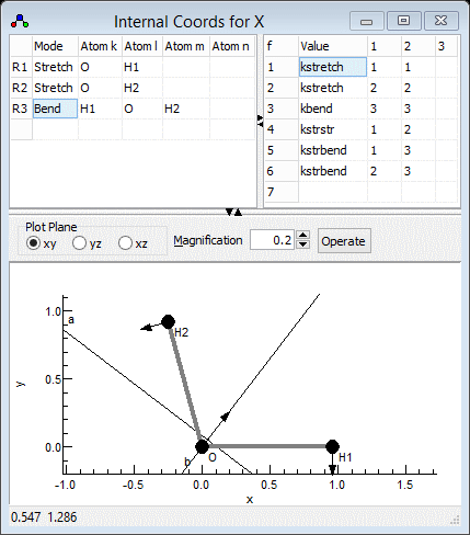
The Internal Coordinates window should look something like the
picture below; the file is available as H2Osf2.pgo.
As the above procedure is followed, a Vibrational
Modes object is added for each vibration with a non-zero
frequency. These are updated from the information in the internal
coordinates and z matrix objects, and the vibrational frequencies
can be read from them. Alternatively, clicking on "Operate"
and selecting "Print" will display the calculation of the
normal modes in the log window. The key information is at the end:
l Matrix (R and T labels arbitrary)
cm-1      3567.5165      3514.9203      1985.2376         0.0001         0.0000         0.0000         0.0000        -0.0000        -0.0000
  l    v1             v2             v3             Rx             Ry             Rz             Tx             Ty             Tz
 xO    0.2158480243   0.1319775701   0.1542439579   0.9538375476   0.0000000000   0.0000000000   0.0000000000   0.0000000000   0.0489314378
 yO   -0.1647853532   0.1728739673   0.2020401264  -0.0627998726   0.1112453333   0.0000000000   0.0000000000   0.4084516430   0.8479316443
 zO    0.0000000000   0.0000000000   0.0000000000  -0.0170374808  -0.8180333414   0.0000000000   0.0000000000  -0.4692857484   0.3321175438
xH1   -0.6805348697  -0.6899365669   0.0581626584   0.2394286284   0.0000000000   0.0000000000   0.0000000000   0.0000000000   0.0122825811
yH1    0.0000000000  -0.0183245689  -0.6814039914   0.0947673725   0.4158240860   0.0000000000   0.0000000000  -0.4805526204   0.3500449461
zH1    0.0000000000   0.0000000000   0.0000000000   0.0000000000   0.0000000000   1.0000000000   0.0000000000   0.0000000000   0.0000000000
xH2   -0.1793620921   0.1641633430  -0.6726408834   0.1328055375  -0.3741846924   0.0000000000   0.0000000000   0.5624645264  -0.1200668167
yH2    0.6564731136  -0.6703720258  -0.1234849642  -0.0448954256  -0.0743106560   0.0000000000   0.0000000000   0.2562049518   0.1766839314
zH2    0.0000000000   0.0000000000   0.0000000000   0.0000000000   0.0000000000   0.0000000000   1.0000000000   0.0000000000   0.0000000000
Discarding 6 modes
The top row has the calculated vibrational frequencies; as
expected three are significant, and are in reasonable
agreement with the observed values considering the approximate
force constants used. Six are essentially zero corresponding to
rotation and translation, though not correctly labelled by this
calculation. The matrix shows the Cartesian displacements along
each normal mode.
Fitting the force constants
We can now fit the force constants to the
observed vibrational frequencies. The first step is assigning the
vibrational modes; the observations are sorted by symmetry,
symmetric modes first, and then frequency but the calculated modes
are only sorted by frequency. The current calculation does not
make any use of symmetry, so a manual step is required to assign
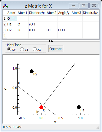
the observed and calculated frequencies. The calculated normal
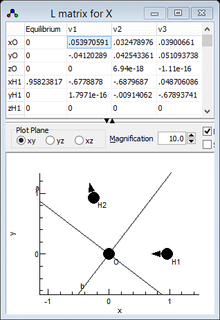
modes are best visualised in the l
Matrix Window; right click on "X" and select "l matrix"
to bring it up. Clicking in a particular column in the top grid
plots the selected mode; clicking on the "v1" column for
example gives the picture below. Note that if you update
information elsewhere you may need to click on "Operate"
and select "Check"to force the window to update. For
heavier molecules you may also want to adjust the magnification
setting to scale up the length of the arrows showing the
vibrational motion.
which clearly shows that v1 is the asymmetric stretch,
ν3 in the experimental paper. Similarly v2
is the symmetric stretch, ν1in the experimental paper
and v3 is the bend. This information can be presented to
PGOPHER by adding the following lines to the observation file
prepared above:
Parameter X.v1.Omega = 3755.79
Parameter X.v2.Omega = 3656.65
Parameter X.v3.Omega = 1594.59
This is available in H2Osf2.obs.
Fitting can now proceed as before:
- Open the log window ("View,
Log...") if it is not open already.
- The text box at the top needs to contain the file name; drag
and drop the file onto the window, or use the browse button to
the right of the text box to bring up a file browsing dialog.
- Make sure the fit type at the top left is set to "Line".
- Given the significant change made to the observations file, it
is probably best to do a fit cycle with no parameters floated to
check that the file has been set up correctly. To fix all the
parameters click on "Fix All" in the constants window.
Pressing the "Fit" button will give
Residuals before fit
    J'S' #'    J"S" #"     Observed    Calculated      Obs-Calc StdDev
X.Bx                        27.8778       27.8531        0.0247 1        :   4:H2Osf2.obs
X.By                        14.5092       14.4168        0.0924 1        :   5:H2Osf2.obs
X.Bz                         9.2869        9.4997       -0.2128 1        :   6:H2Osf2.obs
v1.Omega                  3755.7900     3567.5165      188.2735 1        :   8:H2Osf2.obs
v2.Omega                  3656.6500     3514.9203      141.7297 1        :   9:H2Osf2.obs
v3.Omega                  1594.5900     1985.2376     -390.6476 1        :  10:H2Osf2.obs

6 Observations,  0 Parameters
Average Error: 186.252423387177
suggesting the assignment is correct.
- The obvious first step is to try floating the diagonal force
constants kstretch and kbend. To do
this, click on "Internal Coords" in the constants
window and change the "no" by each of the two
parameters to "yes" by clicking on the "no".
- Pressing the "Fit" button will now carry out one
cycle of least squares fitting. As before a few cycles are
required for convergence, which gives:
Residuals before fit
    J'S' #'    J"S" #"     Observed    Calculated      Obs-Calc StdDev
X.Bx                        27.8778       27.8531        0.0247 1        :   4:H2Osf2.obs
X.By                        14.5092       14.4168        0.0924 1        :   5:H2Osf2.obs
X.Bz                         9.2869        9.4997       -0.2128 1        :   6:H2Osf2.obs
v1.Omega                  3755.7900     3734.6411       21.1489 1        :   8:H2Osf2.obs
v2.Omega                  3656.6500     3678.1439      -21.4939 1        :   9:H2Osf2.obs
v3.Omega                  1594.5900     1594.5436        0.0464 1        :  10:H2Osf2.obs

6 Observations,  2 Parameters
Initial Average Error: 15.0774681419403
Predicted New Error:   15.0774681419403
Parameters:
  # Old                 New                 Std Dev   Change/Std Sens    Summary              Name
  1 7.67120869475949    7.67120869476477    .04415246    0.0000  .005408 7.671(44)            Internal Coords kstretch
  2 .644627021835946    .644627021827996    .01220247    0.0000  .001494 0.645(12)            Internal Coords kbend

Correlation Matrix
       1       2
  1   1.000
  2  -0.002   1.000
- An important check is that the assignment has not changed -
using the l matrix window as above will confirm that the
the highest frequency mode is still the asymmetric stretch.
- The bend is clearly fitting well, but the stretching
vibrations could be improved. This suggests floating the
stretch-stretch interaction might help, and indeed it does:
Residuals before fit
    J'S' #'    J"S" #"     Observed    Calculated      Obs-Calc StdDev
X.Bx                        27.8778       27.8531        0.0247 1        :   4:H2Osf2.obs
X.By                        14.5092       14.4168        0.0924 1        :   5:H2Osf2.obs
X.Bz                         9.2869        9.4997       -0.2128 1        :   6:H2Osf2.obs
v1.Omega                  3755.7900     3755.7900       -0.0000 1        :   8:H2Osf2.obs
v2.Omega                  3656.6500     3656.6500        0.0000 1        :   9:H2Osf2.obs
v3.Omega                  1594.5900     1594.5900        0.0000 1        :  10:H2Osf2.obs

6 Observations,  3 Parameters
Initial Average Error: 0.134714266452586
Predicted New Error:   0.134714266452586
Parameters:
  # Old                 New                 Std Dev   Change/Std Sens    Summary              Name
  1 7.67003365917486    7.67003365917486    .00039448    0.0000  3.22e-5 7.67003(39)          Internal Coords kstretch
  2 .644671760832649    .644671760832649    .00010903    0.0000  8.9e-6  0.64467(11)          Internal Coords kbend
  3 -.0883036398001041  -.0883036398001022  .00039447    0.0000  3.22e-5 -0.08830(39)         Internal Coords kstrstr

Correlation Matrix
       1       2       3
  1   1.000
  2  -0.002   1.000
  3   0.005  -0.002   1.00
- As we only have three vibrations it would be unreasonable to
expect to be able to determine more force constants, so kstrbend
is left at zero. Note that floating kstrbend instead
of kstrstr does give a fit, but with some problems as
the assignment of v1 and v2 become swapped, suggesting this is
not the right approach.
It is now possible to display a variety of
calculated rovibrational parameters such as centrifugal distortion
constants and the vibrational dependence of by right clicking on "X"
and selecting "Print Information". Note that the layout
of object produced by default is a little untidy:
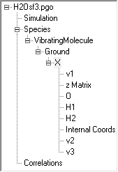
Note the presence of three Vibrational Modes objects (v1,
v2 and v3) and three Nuclear Co-ordinates objects (O,
H1 and H2) all of which are effectively read only in this set-up
as most changes made in these will be overwritten by any
calculation. The order is not important, but the objects can be
re-ordered for clarity; right click on a node and select "Move
Up" or "Move Down". The keyboard shortcuts Alt+Up
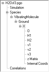
and Alt+Down can also be helpful for this. The final file is
available as H2Osf3.pgo, which
has the following order:
Setting up the symmetry coordinates
It is also possible to add to the above so that
the calculation involves symmetry adapted coordinates. Among other
things, this can reduce or remove the issues with assigning modes.
(Note that the normal mode calculations as currently implemented
do not formally use symmetry so, for example, setting the
point group of the molecule at the molecule level is not
required.) Symmetry coordinates are defined using a Symmetry Coordinates object.
- To create the object, right click on "X" and select "Add
New ..., Symmetry Coords".
- Right click on "Symmetry Coords" and select
"View ..." to bring up the Symmetry Coordinates Window.
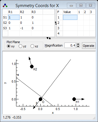
- We now need to enter three symmetry coordinates (S1,
S2, S3) expressed as a linear combination of
the internal coordinates (R1, R2, R3).
This defines the U matrix.. We will try and use the same
numbering for the symmetry coordinates as the experimental
paper, so S1 should be the symmetric stretch.
- The symmetric stretch should be an equal mixture of the two
bond stretches, so S1 = R1+R2. The
coefficients (both 1) are entered in the grid in the top right,
in the top row for S1.
- Enter 1 in the top left cell. When you do this the default
values for all the other coefficients are automatically
entered, corresponding to an identity matrix.
- Enter 1 in the second cell on the top row, under "R2"
- Click on "Operate" and select "Check" to
check and update the plot if necessary. Provided the selected
cell is in the top row, the bottom plot should show the linear
combination of the two stretches. (You may want to use "Apply"
instead, which will update other objects as well.)
- S2 should be the same as the internal bending coordinate, i.e.
S2 = R3. The second row of the grid should
therefore be set to 0 0 1. Blanks can be used instead
of zeros if wanted.
- The asymmetric stretch requires two S1 = R1-R2,
so the third row should contain 1 -1 0.
- Two settings that should probably be set in the "Symmetry
Coords" object are:
- Set PreserveS to true. This tries to
reorder the normal modes so that the numbering is the same as
the symmetry coordinates. This relies on the L matrix, which
relates the normal modes to symmetry coordinates, S =
LQ, having a dominant coefficient in each
column.
- Less important: Set Normalize to true, which
normalizes the symmetry coordinates. in this case the two
stretching modes are divided by sqrt(2).
The symmetry coordinates window should look
something like the picture below; the file is available as
H2Osf4.pgo. Fitting could be done
with this file (with a slightly adjusted input file) though we
don't do this here as the addition of the symmetry coordinates has
made no difference to the final calculated values.
Notes on the symmetry coordinates window:
- Error messages concerning the symmetry coordinates will appear
at the top of the plot. Messages about dpotrf imply that the
symmetry coordinates have not been chosen to be independent; two
identical rows will give this message, for example.
- The force constants can be given in terms of symmetry
coordinates here in the top right grid. When this is left blank,
as here, the force constants are taken from the internal
coordinates.
 Molecule Types Vibrational Structure Force Field Analysis